|
|
Welcome to - Lew's Model Boats - and more! |
go to Home Page |
| LewsModelBoats.org is not a commercial web site. Lew is a scale model builder/hobbiest (model boats and more). Views on this web site are opinions of the author and not driven by any commercial entity. Opinions are welcome - by mailing Lew (see contacts). © Copyright 2023 Lew's Model Boats. Disclosure: This Lews Model Boats do not have any financial ties to any company, political affiliation nor any other subsidy and has no gains from these and any other person(s). Lews Model Boats and this site is purely for the enjoyment of its viewers and others who enjoy this hobby. |
Updated: September 2, 2022
Fire Boat Dusseldorf (FLB 2) - Superstructure Modification
Page is Under Construction
Page is Under Construction
Forward
This site is about Lew's Model Boat's Dusseldorf FLB 2 RC Fire Boat model and the conversion/modification to replicate the real fire boat after the 1979 stretching. In order to do all pertinent information on the real fireboat is/as necessary to help achieve that goal.
On this page we discuss information (what we could find) about the real fire boat perhaps not necessary to reconstruct the superstructure to ~year 2022. Some of the changes reflect kit errors while others might be changes made to the real boat's superstructure ove the years. As we could not find many old photos, determination could not be made as to errors or upgrades in most instances.
Disclosure: A lot of work went into developing the drawings and this procedure
andto the best of my ability I have made this as accurate as possible using mostly photos. The might be som small
discrepancies between scaling the real boat and the information here but I think not enough to be noticable.
The Superstructure is far from Being Accurate
Unless a vessel is well researched by an expert, errors will be made in the conversion of data from a real boat into makeing a model or kit. This is
particuarly true in the case of the Düsseldorf kit.
This is the basic kit, not the hull lengthening process or
modernization.
Take a look at this... notice the difference?
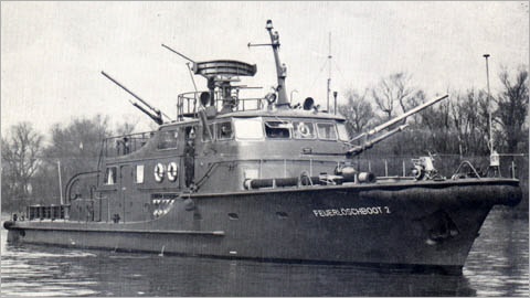
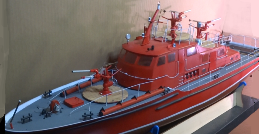 The real boat as originally built and modelled after (above, left), has five individual windows across the front. The model (above, right) has
only three. And, the proportion of width to height of the windws is off quite a bit. This is only one of a number of inaccuracies in the superstructure.
The real boat as originally built and modelled after (above, left), has five individual windows across the front. The model (above, right) has
only three. And, the proportion of width to height of the windws is off quite a bit. This is only one of a number of inaccuracies in the superstructure.
Here is another gaping difference between the original build Dusseldorf and the kit. (Photo, right) Wonder why the real boat looks like it is sitting lower in the water than the original? That is because the kit's hull (along the main deck) is sitting 1/2 inch (12.7mm) too high. The difference between the fore (front) deck and the main deck is 7/8 inch and should be 1-3/8 inch.
This can be cured and is covered under the hull modifications on this site. (The middle and aft sides of the hull must be cut down 1/2 inch and the strakes be moved as well. The side of the superstructure is very close to the right height so the height of the cutout along superstructure's side where the steps from the main deck to the fore deck are located has to be raised from 7/8 inch to 1-3/8 inch.)
Take a look at this... notice the difference?
Here is another gaping difference between the original build Dusseldorf and the kit. (Photo, right) Wonder why the real boat looks like it is sitting lower in the water than the original? That is because the kit's hull (along the main deck) is sitting 1/2 inch (12.7mm) too high. The difference between the fore (front) deck and the main deck is 7/8 inch and should be 1-3/8 inch.
This can be cured and is covered under the hull modifications on this site. (The middle and aft sides of the hull must be cut down 1/2 inch and the strakes be moved as well. The side of the superstructure is very close to the right height so the height of the cutout along superstructure's side where the steps from the main deck to the fore deck are located has to be raised from 7/8 inch to 1-3/8 inch.)
The Process
In this case it will be simplier to build a new structure rather than modifying the kit's superstructure. Steps will be listed in
the order the resoration will take place.
| Step | Process |
| 1 | Collect Data (drawings, photos, etc.) |
| 2 | Layout Drawing using Collected Data |
| 3 | Transfer Drawing Data to the Plastic (Styrene-recommended, or other material) |
| 4 | Drawings - description, identification, and download links |
| 5 | Cut, drill, etc. Parts |
| 6 | Assemble Parts |
1. Collect Data
First
one needs to collect the data. I have not found any
drawings so I am using as many photos as possible to scale
the details and convert them into drawings which will be
used for fabrication. To make it easier for anyone
wnating to convert their FLB 4 into a corrected version I
will have them on this site from free. No need to go
through all that work repeating what I did.
2. Layout Drawing
Once the drawings are made they can be used to fabricate
parts. The drawings are at 1/1 scal for the 1/25
model. Please refer to original photos of the real FLB
2 to get more information of what you are building and this
also aides in interpretation of the drawings.
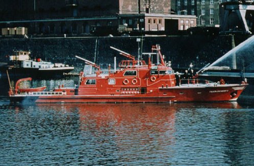
I found a good side view of the FLB 2, probably as good as it gets. I then enlarged it to meet the dimensions I could determine as being the right size of the side of the superstructure. From this i was able to locate the details from the doors and windows down to the location of the handrail posts. Once those were determined I made the drawings (X-Y coordinates) and then double checked by superimposing the plotted CAD drawing on the photo.
Videos might become available at some point in the future. (Drawings/photos to be added.)
3. Transfer Drawing Data to the
Plastic Material
 With the full scale drawings you can either
transfer the information from them to the materials or
use them as templates, or more likely both metheods.
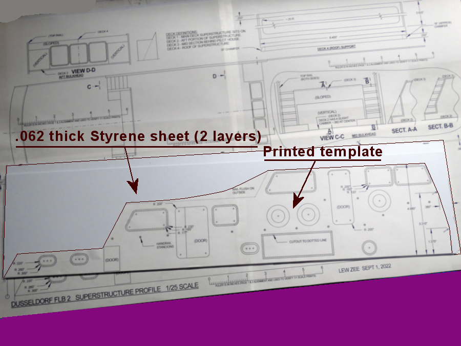
Note that the sides of the superstructure are not
parrallel for the entire length. The forward
portion sides are parrallel but approximately in the
middel the side curve in slightly, and this is
identified on the drawings. This is identified on
the drawing.
With the full scale drawings you can either
transfer the information from them to the materials or
use them as templates, or more likely both metheods.
Note that the sides of the superstructure are not
parrallel for the entire length. The forward
portion sides are parrallel but approximately in the
middel the side curve in slightly, and this is
identified on the drawings. This is identified on
the drawing.(Photo, right) First step is to cutout the templates (or you can measure and transfer the data) and tap to two layers of the Styrene sheets). This will make both sides at the same time. Double sided tape works well for both the two sheets and the template.
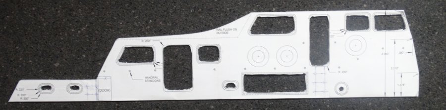 (Photo, left) Here is what the trimmed side panels
(pair laminated for cutting at the same time) looks
like. The outline has been smoothed and handrail
pilot holes drilled and other cutout roughted out.
(Photo, left) Here is what the trimmed side panels
(pair laminated for cutting at the same time) looks
like. The outline has been smoothed and handrail
pilot holes drilled and other cutout roughted out.(More drawings/photos/instructions to be added.)
4. Cut,
Drill, etc. Structure Parts
Cut
the coutline of the structure. When cutting the curved
area use the dotted line for the edge of the side panel as
the handrail will be added later. Next drill all the
holes and make the cutouts in the order you choose.
The window cutouts are the dotted lines. Bthe solide
lines are the inside and outside of the bezels.
Follow the same procedure for the bulkheads and structure ends. The forward end will require cusomization as it is composed of multiple pieces, the bottom band, middle band , and the panels for the windshields (which are seperate pieces).
(Drawings/photos/instructions to be added.)
Follow the same procedure for the bulkheads and structure ends. The forward end will require cusomization as it is composed of multiple pieces, the bottom band, middle band , and the panels for the windshields (which are seperate pieces).
(Drawings/photos/instructions to be added.)
5. Assemble
Parts
Test
fit all parts before cementing. (Drawings/photos to be
added.)