|
|
Welcome to - Lew's Model Boats - and more! |
go to Home Page |
| LewsModelBoats.org is not a commercial web site. Lew is a scale model builder/hobbiest (model boats and more). Views on this web site are opinions of the author and not driven by any commercial entity. Opinions are welcome - by mailing Lew (see contacts). © Copyright 2024 Lew's Model Boats. Disclosure: This Lews Model Boats do not have any financial ties to any company, political affiliation nor any other subsidy and has no gains from these and any other person(s). Lews Model Boats and this site is purely for the enjoyment of its viewers and others who enjoy this hobby. |
USCG 47-ft Motor Life Boat
Updated January 5, 2023
Updated January 5, 2023
Forward
This model is a 1/18 scale (about 30-3/4 inches long) and was a ready to run (RTR) model made by ProBoat. It was given to me in
June 2021 as the original owner did not have a need for it. I was in a generally OK condition, a little dirty, some parts broken off (none missing) and the
old FM transmitter and
receiver did not function.
The hull and cabin is made of fiberglass. Most of the detail parts are made of resin and the interior bulkheads and mounting platforms made of plywood with a varnish coating. As for a scale appearance, overall it looks good. The real boats had an aluminum finish where as this model is finished in white. Some of the details are of low quality. This includes a number of vents and hatches that are simply printed on clear labels and stuck on the boat. The windows are also stickers, although they don't look terribly bad.
Functionally, the boat is fast but does not handle well. One of the problems is that both motors and propellers turn in the same direction causing the boat to walk slightly to the right. Making a left turn takes about half the diameter than a right turn, caused by the propellers rotating in the same direction. Also, the boat does not move slowly. When moving the speed control stick the boat moves slightly faster than desirable. When running with the lights on, all lights blink. The navigation light should stay on continuously.
This is my first RTR boat. Normally I would not have one
because they are usually not made to scale, however this one is!
Below you will see a number of improvements/modifications that I made to improve the look and function of the boat.
With the control stick at the lowest speed setting the boat moves
much faster than desirable. When running with the lights on, all lights blink. The navigation lights should stay on continuously
and not blink.I am also including links to some of my 3D files so you can update your 47ft MLB (free).
The Boat as Received and Updated
Below are some comparison photos of the MLB as
received (left
side) versus the finished boat:
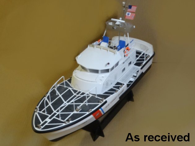
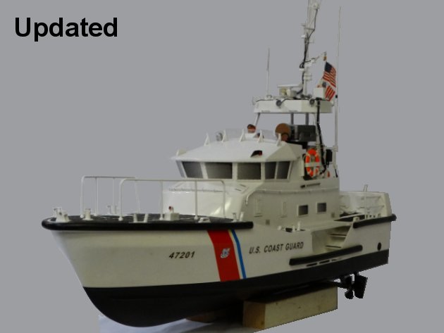
As Received (above and below) As modified by me (above and below)
Internal and External Functional Improvements
Motor Couplings Replaced. The boat's original connection between the two motors and two shafts was a solid coupling with the motors factory shimmed in place. Upon removing the
couplings (one was frozen and had to be cut-off) it was hard to get it directly aligned. They were replaced with Dumas "Dog-bone" (double universal joints) and in doing so the
motors had to be moved forward about 1-1/8 inches requiring new motor mounts and the bulkhead cut away.
Counter-rotating Propellers. Rather than have the two propellers rotate in the same direction [ugh] I reversed the direction of one of the motors and replaced the propellers with Graupner 42mm diameter left and right hand propellers. These were about 30% larger in blade surface areas.
Replaced the 27mhz radio (transmitter and receiver) with a Spktrum 8-channel 2.4ghz system.
Added a catch and neoprene foam gasket to the underside of the superstructure to hold and seal it in place. Aft deck removable section now has a watertight bulkhead under it.
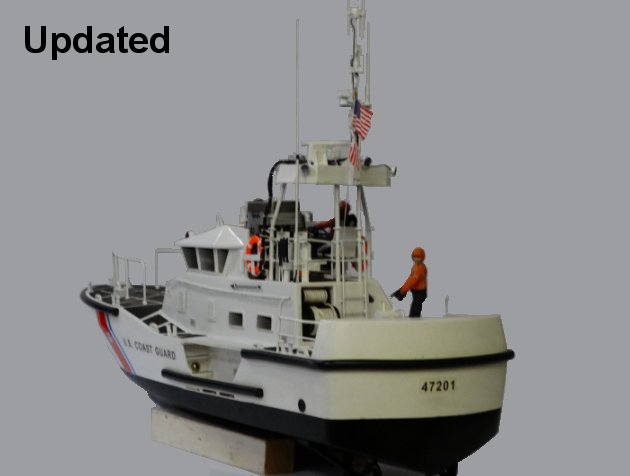
External (visual) Improvements
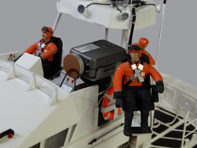
Below left (first photo) the figure and seat is removed (figure is in the middel if the photo) to make way for a Run-cam camera. The
camera is mounted on a servo so the camera can back and forth at "eye" level. It is easily removable to replace the figure in position. The secon photo shows the details
added to the inside of the transom. This is where decals were used to similate the hatches.
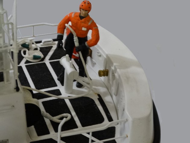
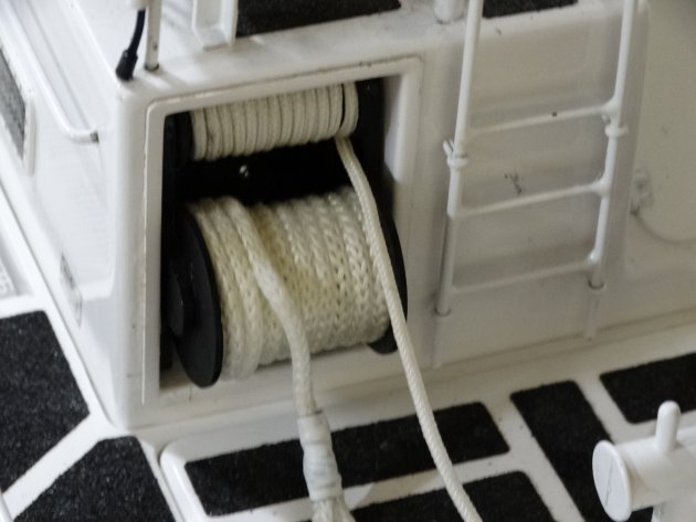
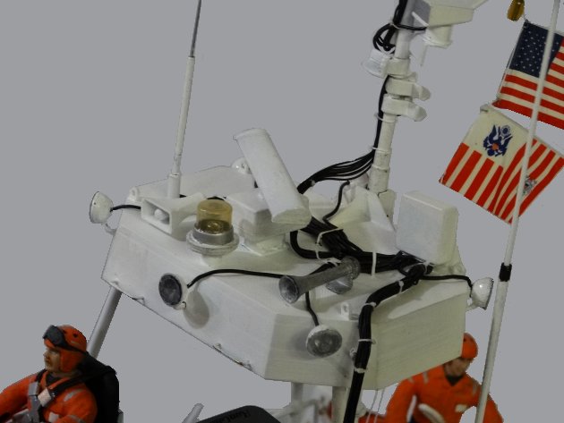
The third photo show the anchor hatch added to the forward deck. The fourth photo shows the jump seats used to replace the model pathetic ones. The fifth photo shows the rescue tow lines with new "ropes" which replaced the original ones that were the same size an wound on one reel to the other. The sixth photo shows the top side of the new 3D printed float chamber with added details. These external wires are non functioning. The radar turns and the lights work. (The top left photo shows a camera in place for videos. Normally, the crew member in the seat, shown, is in that place.)
The third photo show the anchor hatch added to the forward deck. The fourth photo shows the jump seats used to replace the model pathetic ones. The fifth photo shows the rescue tow lines with new "ropes" which replaced the original ones that were the same size an wound on one reel to the other. The sixth photo shows the top side of the new 3D printed float chamber with added details. These external wires are non functioning. The radar turns and the lights work. (The top left photo shows a camera in place for videos. Normally, the crew member in the seat, shown, is in that place.)
Oops - it Sank!
On March 6, 2022, at the regular meet of the Suncoast Scale Model Boat Club this model sank. Not completely, but about
95% of the boat was underwater hanging only by "a thread" with
only about two inches of the bow above water.
The boat was busy taking some video and I left it stay idle while I chatted with some other model boaters. I happened to turn around and the boat was completely on its side (about 50/50 on top and below the water, about 120 feet from the shore. I brought the rescue boat out (which was in the water and by that time it was "nose up". Knowing that I could not push it as thre was no way to get a grip on it I returned the rescue boat to the dock and fitted the "U" shaped yoke on to the bow.
By the time I got out to the CG boat it was only sticking its nose about 4 inches out of the water. I could see it continue to sink as I moved it forward toward me (on the dock). Luck was with me as when I was able to grab the bow that was sticking only about 2 inches out of the water and ready to slip under. The superstructure had fallen off but the servo cable between the receiver and the camera base was the "lifeline."
The boat was taken home and cleaned, as it was absolutely a mess. All of the parts surrvived, some broken but nothing missing. The rudders were damaged but the RC receiver (Spektrum) at first was thought to be a loss, but taken apart, cdried and cleaned and it still works! The inside is being rebuilt with much more floatation. What really saved the boat was the small amount of floatation I stuffed into the bow last year. It kept the boat afloat enough to retrieve it. It would not had stayed afloat another 5 minutes.
The gator water in the pond is completely filthy and not very healthy plus the danger of gators would have prevent me from going in after it. There are a number of ponds in Florida that have micro-organisms that are dangerous to human health.
Links for Some of my 3D printed parts
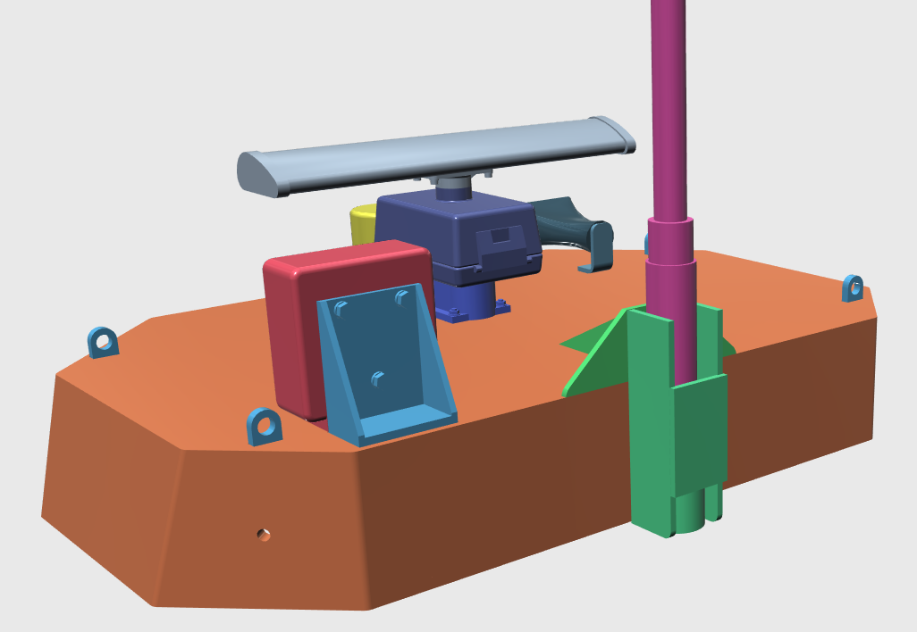
Unfortunately I do not have any photos of the interior of the upper floatation chamber. Basically it is use to make junctions for the livewiring
that comes up through the chamber pipes (vertical supports that space the chamber off of the superstructure) and connects to the wiring to the radar motor, flashing blue
light, and running lights. All of the other lights are non-functioning. The exterior wires (black) are non-functioning as they are single conductor. Download files for the 47 ft MLB:
| File name | Description |
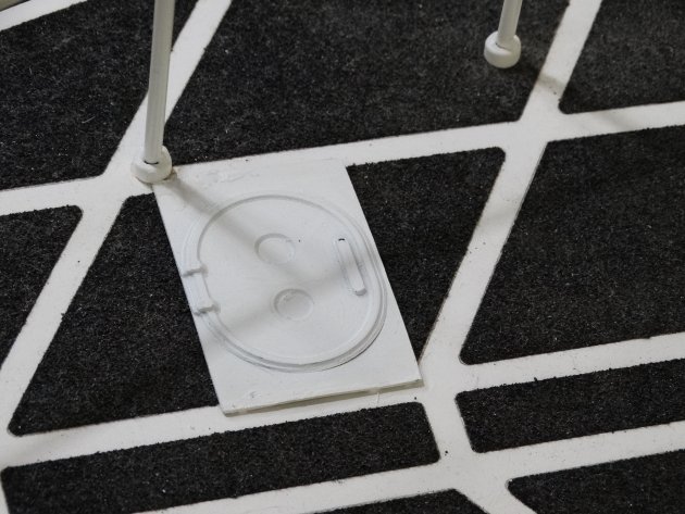
| Download CG-47-anchor-hatch.stl | This is the anchor hatch located on the fore deck. Cement in place on top of the anti-slip coating. |
| Download CG-47-Cabin-side-vent-small.stl | This is the small vent on the sideof the cabin. Port side only. Replaces stickers. |
| Download USCG-47-Cabin-side-vent-large.stl | This is the large vent on the sideof the cabin. Both sides. Replaces stickers. |
| Download CG-47-Transom-Storaged-Door.stl | This is the door (hatch) located on the inside of the transom. (3 required.) Replaces stickers. |
| Download CG-47-Upper-floatation-chamber.stl | This is the upper floatation chamber. It is open on the bottom to access the inside. Cover below. |
| Download CG-47-Upper-floatation-chamber-horn-lights.stl | These are parts for the upper floatation chamber. |
| Download CG-47-Upper-floatation-cover.stl | This is the upper floatation chamber cover. Fastenes to the under side of the chamber with four screws. |
| Download CG-47-Upper-Floatation-parts.stl | These are parts for the upper floatation chamber. Some are duplicates of the above. |
| Download USCG-47-Jump-Seat.stl | New jump seat set for upper deck. More realistic looking. |
| Download USCG-47-Seat-for-printing.stl | New front seat for upper deck. More realistic looking. required. |
| Download USCG-47-Motor-Mount.stl | Motor Mount for converting to installing Dumas "Dog-Bones" universal joints (2 required) |
Seats
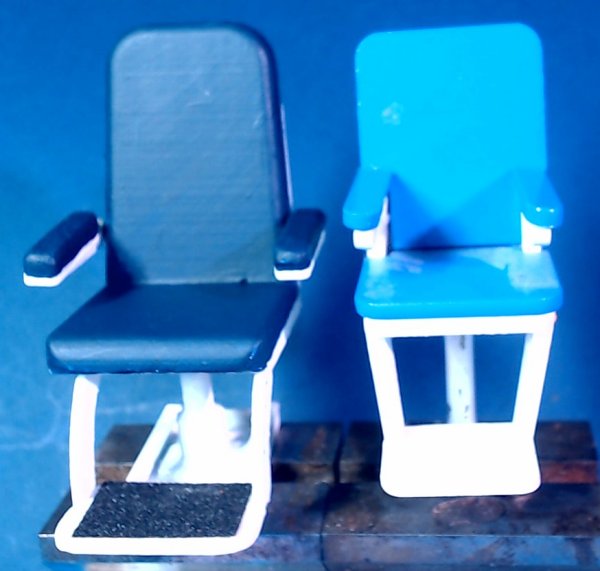 Four seats were replaced by 3D printed ones.
The bridge crew seats and the jump seats are all located on the upper deck. The crew seats are forward by the controls and the jump seats are under the
upper floatation chamber facing the center of the boat.
Four seats were replaced by 3D printed ones.
The bridge crew seats and the jump seats are all located on the upper deck. The crew seats are forward by the controls and the jump seats are under the
upper floatation chamber facing the center of the boat.nbsp;
The crew seats were completely wrong in syle, color, and they would not hold 1/18 scale figures, at least the ones I added. At the right uyou can see a comparison between the new (left) and the old (right) seats. The arm rests can fold up if not cemented in place.
The pair of jump seats were equally not even close in appearance. The ones I created are much closer but not exact (kind of simplified).
Motor Mounts
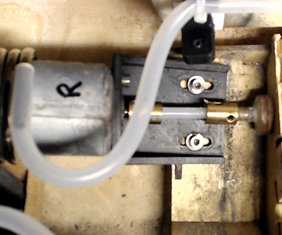 The two ProBoat motor mounts were replaced by 3D printed mounts. The reasoning is that the original mounts had a direct coupling to the prop shaft requiring an exact
alignment. Because the motors were removed because one of the coulings was "frozen" I decided to use a universal joint.
The two ProBoat motor mounts were replaced by 3D printed mounts. The reasoning is that the original mounts had a direct coupling to the prop shaft requiring an exact
alignment. Because the motors were removed because one of the coulings was "frozen" I decided to use a universal joint.With many years of experience in using the Dumas "Dog-Bones" couplings, even in much larger boats, and knowing they were very reliable, they were choosen for the replacements.
Because this increased the distance between the motor and the prop shaft two things had to be done. First the plywood bulkhead at the termainal end of the motors had to be opened up for the relocation of the motors further forward. Second, the motors needed a new bracket.
So this new bracket (3D printed in ABS) is compatible with the motor mounting holes, the mounting hulls in the hull, and the additional length added by the use of the "Dog-Bones". No other modifications needed. There are slots for all the screws, but they fit pretty much in the center of the slots.
Electronics/Schematic
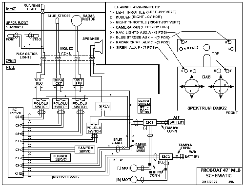 Yours will probably be different, but
here is mine using an 8 channel receiver and transmitter. Select the picture at the right to download a printable PDF.
Yours will probably be different, but
here is mine using an 8 channel receiver and transmitter. Select the picture at the right to download a printable PDF.As of this printing the electroncics and enclosure have not been completed and installed.
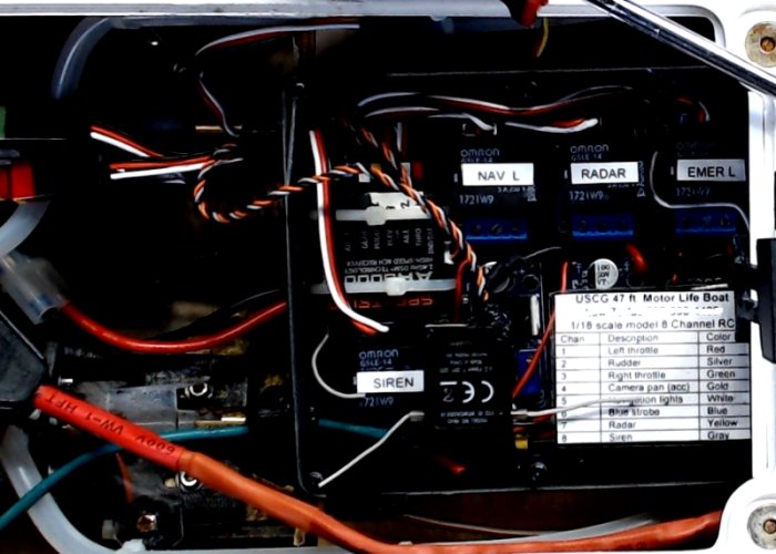
This is for eight channel operation as follows:
| Channel (Spektrum DX8 & AR8000) | Function |
| 1 | Left motor throttle (ESC - BEC to receiver) |
| 2 | Rudders (servo) |
| 3 | Right motor throttle (ESC - BEC is cut) |
| 4 | Camera pan (servo moves camera) |
| 5 | Navigation lights (on structure and mast) (channel relay switch) |
| 6 | Blue strobe (on top of floatation chamber) (channel relay switch) |
| 7 | Radar drive (inside floatation chamber) (channel relay switch) |
| 8 | Siren (speaker is inside superstructure) (channel relay switch) |
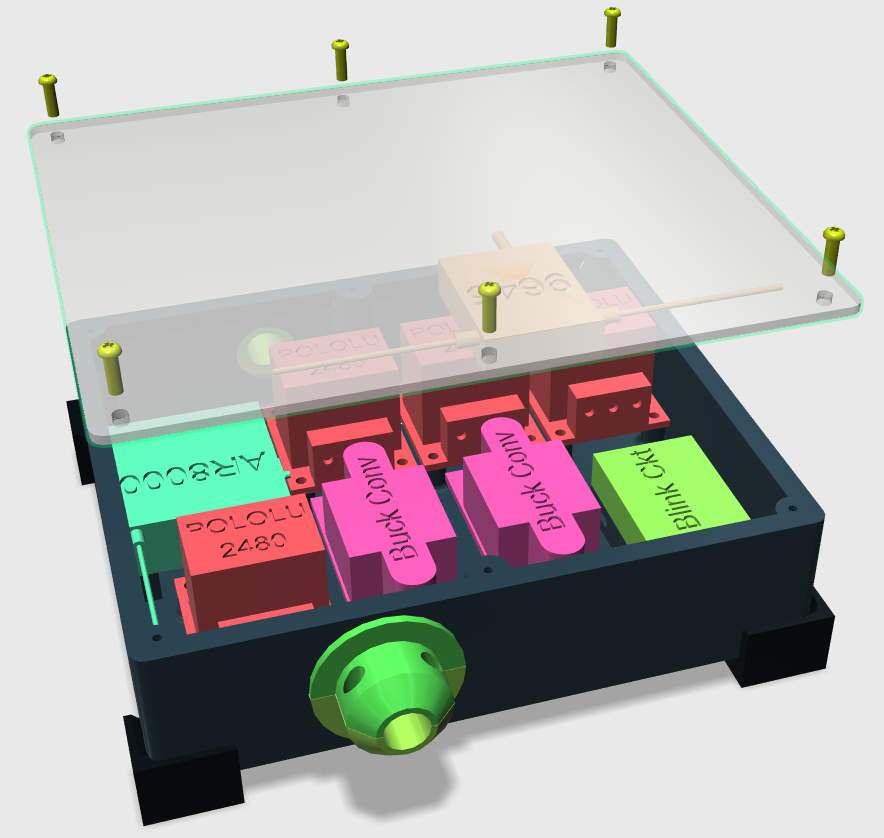 The 3D printed
Electronics Enclosure will contain the electronics modules that are located in the hull. This includes: The AR8000 receiver and satelllite, four Pololu
relay seitches, two buck voltage conerters (for the LEDs), and one blink circuit (for the blue "strobe" light).
The 3D printed
Electronics Enclosure will contain the electronics modules that are located in the hull. This includes: The AR8000 receiver and satelllite, four Pololu
relay seitches, two buck voltage conerters (for the LEDs), and one blink circuit (for the blue "strobe" light).The enclosure has a watertight cover and the wires will go through hubs that will be sealed with silicon sealant. The 3D model is at the right and the 3D printed, assembled and wired box is below. The box is easily removable by using spring tension hold down clips to make it easy to change out the aft battery.
Sinking Protection Floatation
& Sealing
After suffering the anxiety of alomost loosing this boat I decided to add sufficient protection floatation to keep it afloat in case of an
accident. Included here will be some hatch sealing information as well.
Floatation was added to the hull in several areas. All of the floatation is concealed behind thin plywood bulkheads and covers which are removable should the inside needs to be cleaned, repaired, or modified.
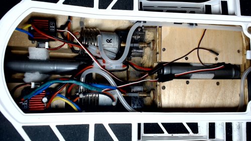
 ←This first photo is looking forward where the bow was stuffed with foam (you can see the white foam).
It is in multiple layers so that they can be pulled out in order from top to bottom should internal access be needed.
←This first photo is looking forward where the bow was stuffed with foam (you can see the white foam).
It is in multiple layers so that they can be pulled out in order from top to bottom should internal access be needed.
At the bottom right of the photo it is hard to see part of the starboard floatation compartment's plywood cover (under the ESC's) that is removable should access be need there. The port side was the same configuration. Both are filled with removable foam.
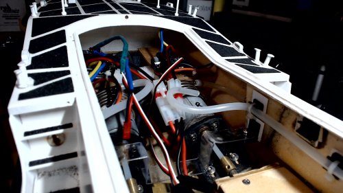
 ←This second photo wais looking down (tilted slightly aft) at the entire opening under the superstructure. The middle bulkhead (where the phop shafts are supported) has been thickened with
the addition of another piece of 1/8 inch plywood. Behind that (moving to the right) you can plainly see two more floatation boxes that are filled with removable foam. They
are also removable.
←This second photo wais looking down (tilted slightly aft) at the entire opening under the superstructure. The middle bulkhead (where the phop shafts are supported) has been thickened with
the addition of another piece of 1/8 inch plywood. Behind that (moving to the right) you can plainly see two more floatation boxes that are filled with removable foam. They
are also removable.
Both batteries now sit on their sides which lowers the center of gravity to help stabilize the boat. This also now give more room for the electronics enclosure (not installed here) as the shelf is 3/8 inch lower.
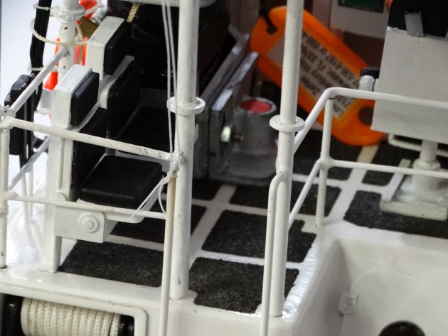
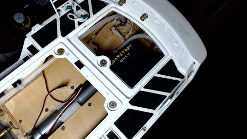 ← This third photo is looking aft. The entire raised transom area is filled with reovable floatation foam and held in
place with a small support to keep it from falling down on to the rudder posts.
← This third photo is looking aft. The entire raised transom area is filled with reovable floatation foam and held in
place with a small support to keep it from falling down on to the rudder posts.
There is also removable floatation foam under the servo plate, and that can be pulled forward for access at that point.
All totaled, the floatation inside the hull should displace well over 12 pounds.
Floatation was added to the hull in several areas. All of the floatation is concealed behind thin plywood bulkheads and covers which are removable should the inside needs to be cleaned, repaired, or modified.
←This first photo is looking forward where the bow was stuffed with foam (you can see the white foam).
It is in multiple layers so that they can be pulled out in order from top to bottom should internal access be needed.At the bottom right of the photo it is hard to see part of the starboard floatation compartment's plywood cover (under the ESC's) that is removable should access be need there. The port side was the same configuration. Both are filled with removable foam.
←This second photo wais looking down (tilted slightly aft) at the entire opening under the superstructure. The middle bulkhead (where the phop shafts are supported) has been thickened with
the addition of another piece of 1/8 inch plywood. Behind that (moving to the right) you can plainly see two more floatation boxes that are filled with removable foam. They
are also removable.Both batteries now sit on their sides which lowers the center of gravity to help stabilize the boat. This also now give more room for the electronics enclosure (not installed here) as the shelf is 3/8 inch lower.
← This third photo is looking aft. The entire raised transom area is filled with reovable floatation foam and held in
place with a small support to keep it from falling down on to the rudder posts.There is also removable floatation foam under the servo plate, and that can be pulled forward for access at that point.
All totaled, the floatation inside the hull should displace well over 12 pounds.
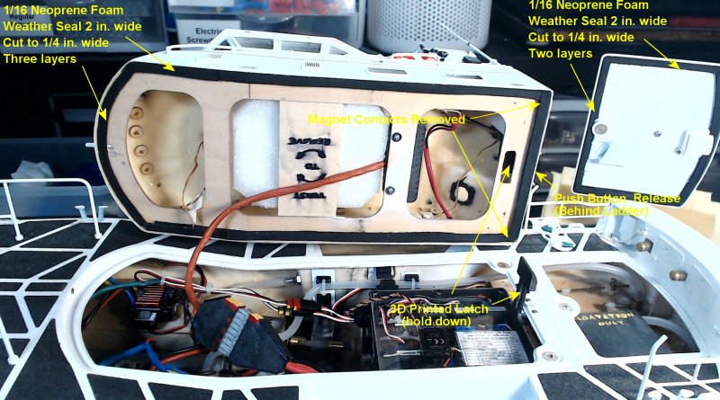 Floatation and a sealing gasket was added to the superstructure:
The piece of floatation (foam) is held in place and is easily removable. The sealing gasket actually is located around the perimeter of the superstructure on the under side. I used 3 layers of 1/16 neoprene weather seal foam (adhesive one side). The foam was 2 inches wide (best price) and I had cut sections of it to 1/4 inch wide stacking three layers. This seems to be the best thickness allowing a bit of compression. I 3D prited a hold down latch which has a release button behing the aft ladder.
A sealing gasket was added to the aft deck removable section.
You can also see the 1/8 inch thick (two layers of 1/16 inch neoprene foam) 1/4 inch wide for a sealing gasket that was added to the underside of the rear deck (hatch). This is held down with a little catch made out of styrene that is slid in from the superstructure opening under the main deck.
Water Sealing Test
br /> Well, after a dunk test (the complete aft end of the boat was submerged with the deck about 2 inches (50mm) above the deck. Water still came inside!!! I don't know if it was the aft deck, superstructure, or both.
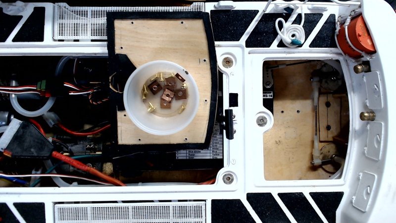
Moving on, I removed all of the sealing gasket and hold down under the aft deck section. I traced the outline of the opening onto card stock and added 1/4 inch (6mm) around the edge and transferred that onto a piece of 1/8 inch hobby grade plywood (reinforced with more 1/8 inch plywood on the bottom side about 1/2 inch around the perimeter for the screws to grip into. On the top side I added one layer of the same 1/16 inch thick neoprene foam gasket tape about 1/4 inch wide. (Lower left photo.)
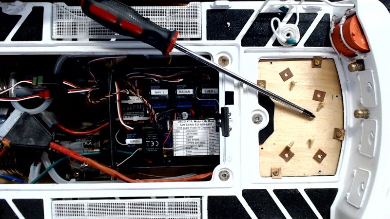
The new bulkhead is placed under the deck and slid back into position and is held in place with 8 #4 X 3/8 inch brass wood screws and square washers which catch the lip of the fiberglass deck. Tighten the screws to compress the gasket (lower right photo). This should be a good seal. The original aft deck is then placed in position using the magnet to hold it in place.
Next step is to water test this again.
br /> Well, after a dunk test (the complete aft end of the boat was submerged with the deck about 2 inches (50mm) above the deck. Water still came inside!!! I don't know if it was the aft deck, superstructure, or both.
Moving on, I removed all of the sealing gasket and hold down under the aft deck section. I traced the outline of the opening onto card stock and added 1/4 inch (6mm) around the edge and transferred that onto a piece of 1/8 inch hobby grade plywood (reinforced with more 1/8 inch plywood on the bottom side about 1/2 inch around the perimeter for the screws to grip into. On the top side I added one layer of the same 1/16 inch thick neoprene foam gasket tape about 1/4 inch wide. (Lower left photo.)
The new bulkhead is placed under the deck and slid back into position and is held in place with 8 #4 X 3/8 inch brass wood screws and square washers which catch the lip of the fiberglass deck. Tighten the screws to compress the gasket (lower right photo). This should be a good seal. The original aft deck is then placed in position using the magnet to hold it in place.
Next step is to water test this again.